Sleeving Valves and Other Heroic Measures
Most old brass instruments are not worth the cost of labor to repair or restore them, but on the high end of the spectrum, there are some so rare and desirable, that they find an owner willing to spend what is necessary to bring them back from the brink. I've covered a few other such restorations, such as the Eisenbrandt double cornet,Teltow cornet and other one of a kind relics, but in this case an almost identical instrument exists to know the design of the missing parts.
These are Eb tubas made by Graves & Co. in Boston in the mid to late 1850s. The complete example in the belongs to Mark Elrod and the other is in the collection of Steve Ward. It's flattering to know that Steve thinks that I can repair or reproduce anything, but the expense of the many hours involved in this project exceeds the sensibilities of most collectors.

Mark Elrod’s complete Graves tuba.
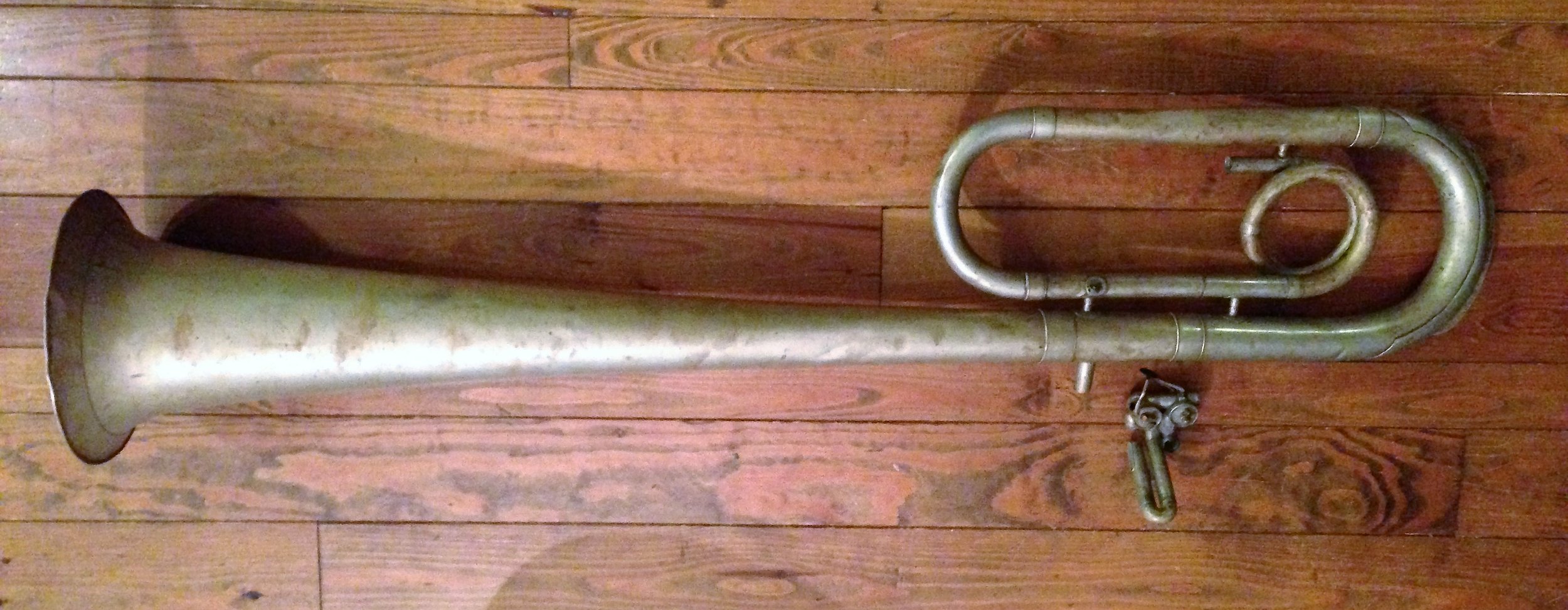
Steve Ward’s Graves tuba as found.
The third photo shows some of the steps involved in reproducing the missing valve casings, but the subject of this page is the much simpler process of installing a sleeve on a valve to restore its intended function. Notice that one knuckle is also missing from the second valve casing. This was replaced with one newly made before proceeding with the repair of the rotor.

Casings being made for Graves tuba restoration.
It is a matter of course that many valve rotors or pistons will need to be built up with plating and refit to the casing to make them air tight once again, but when the amount of build up exceeds .010", the plater must build up plating and hone several times before achieving this result. In rotary valves, this is even more labor intensive, necessitating repeatedly hand lapping the increasingly rough build up of plating. A fairly simple solution, taught to me by the great Los Angeles repairman from my youth, Larry Minick, is to solder a sleeve on to the valve to make up the needed dimension. In my experience, this is most often needed in the case of piston valves that have been dented and otherwise damaged well beyond normal wear and tear, but I have also used this technique on rotary valves, as shown here.
At some point in the usage of this tuba, the second valve rotor must have been lost or badly damaged and the solution was to put the fourth rotor in its place and remove the entire fourth valve and related tubing. It probably didn't play very well at that point, since the replacement rotor was undersize compared with the intact first valve which was still acceptably tight as I found it.
The first step in this process is to carefully examine and measure both the rotor and casing to determine what needs to be done. The bearings were fitting well, but the clearance between the rotor and casing ranged from .007" to over .012", the variance being in the out of round casing and a low spot in the rotor. Even though the valve body and bearings were fairly concentric, I decided to machine the rotor body in order to make the wall thickness of the sleeve enough for reliable rigidity. This involved making accurately fitting brass collets or adapters as seen in the next two photos. One of these has a split in it to clamp the stem in the lathe collet and the other is long enough to engage the tailstock center.

Brass collet and sleeve made to fit stems.

Brass collets installed on stems.
I carefully checked that the valve body and bearing were centered using a dial indicator.

Checking rotor body with dial indicator.

Turning rotor body undersize to accept sleeve.
After machining the body to the desired diameter, I made a sleeve with a good slip fit for soldering and the outside diameter about .01" larger than the finished dimension.

Sleeve made to fit rotor body.
As I slid this over the rotor, I inserted steel ball bearings onto each port for ease of locating the holes.
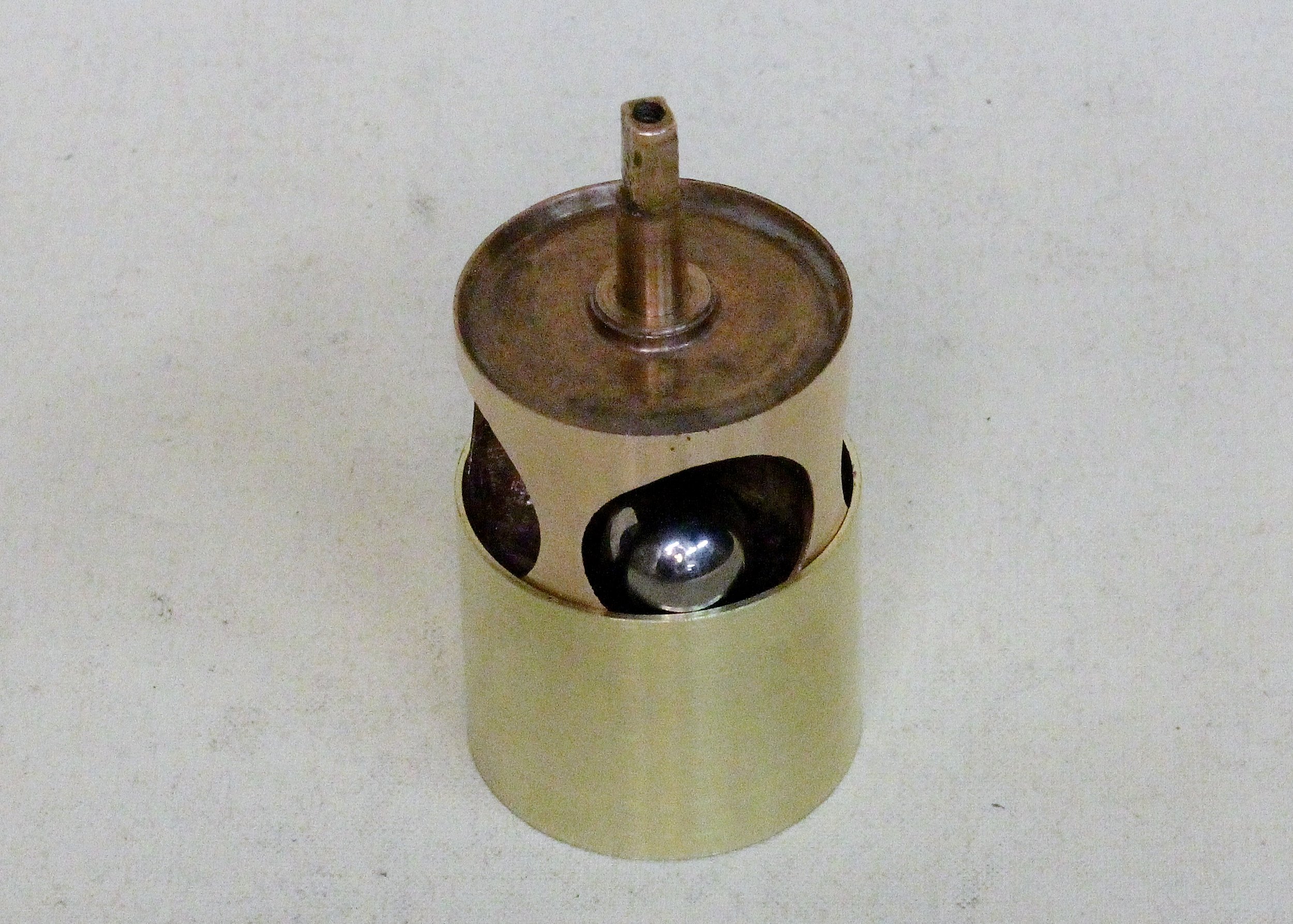
Insert steel balls in ports as sleeve is slid in place.
After soldering, I used a magnet to locate where the holes needed to be cut in the sleeve. The result is shown in the tenth photo. Using the same brass collets, I machined the sleeve to a slight taper matching that of the casing.

Sleeve soldered over rotor body.
Because I want to lap this into the casing, I made it about .003" oversize. If the casing was in better condition, I would have made this only .001" or less. The next photo shows the rotor after machining, but before lapping.

Rotor body machined oversize to be lapped into casing.
If this were a piston valve, it is best to hone it to size at this point. The next photo shows the valve after the final lapping along with the rest of the valve parts, original and newly made. You can see that the first valve needed no lapping at all.

All valve parts ready for mounting and then assembly.
The last photo shows the valve assembly assembled with original second valve lever and three newly made to match.

Valve section in restored Graves tuba.
The rest of the photos show the same process on a piston valve. In this case, the piston was a replacement from another cornet that had the exact port positions as the one being restored, but was about .010" undersize. This could be built up with plating, but this is an excessive amount. While the ports could be masked to eliminate the build up inside them, I prefer not to mask port in antiques. The extra abrasive cleaning of the ports after plating and scraping the edges could cause it to leak at that point.
I made brass plugs for each end. The long, narrow one, fits snugly into the spring barrel so that it won't collapse when gripped in a collet.

Plugs made to fir piston bottom and spring barrel.
The other will be soldered into the bottom of the piston and then center drilled as seen below.

Plugs inserted in piston.
After determining how much wall thickness I can safely remove and find a nickel silver tube for the sleeve, I mount it in the lathe and machine to fit the sleeve.

Piston mounted in lathe before cutting.

Piston and sleeve machined to fit.
As I slide the sleeve on the piston, I place a steel ball bearing in each port. The ball should be as large as will roll through the port.

Insert steel balls as sleeve is slid in place.
Using a strong and thin magnet, locate and mark the approximate center of each port, then cut the holes.

Centers of holes marked after locating with magnet.
I use a small jewelry type of hand grinder with a small abrasive wheel to start, a burr to open them further and finish, very carefully, with a scraper. Great care must be taken to avoid cutting into the port or piston wall. It may be necessary to add some solder, if the original piston had deep dents, causing gaps.

Port holes cut to size.
This is then machined to a diameter that can easily be honed to size.

Cutting piston sleeve to correct diameter for honing or lapping.
If there is no honing machine available, it is more difficult to achieve as good a fit.

Finished piston after lapping into casing.
Even without plating or honing to size, with a well tuned lathe and very careful work, the piston can be machined close enough to lap into the piston and be an acceptable fit for playability.